
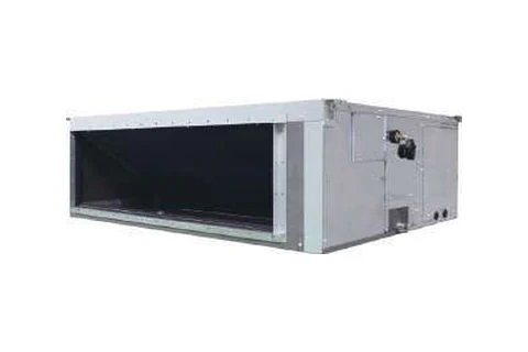
FXMQ200PVM is a Daikin indoor unit in the FXMQ-P series, concealed ceiling ducted high static pressure type. Its rated cooling capacity is 22.4 kW according to catalogue PCVVN2507Aaprv.
- Rated cooling capacity
- 22.4 kW
- Power supply
- 1-phase, 220-240 V/220-230 V, 50/60 Hz
- Dimensions (H×W×D)
- 470×1,490×1,100 mm
- Weight
- 95 kg
Data extracted from the English catalogue; not all specifications have been manually verified. Check the source before use. Source & notes →
FXMQ200PVM specifications
| Rated capacity 4 specifications | |
|---|---|
| Cooling capacity · Btu/h | 76,400 |
| Cooling capacity · kW | 22.4 |
| Heating capacity · Btu/h | 85,300 |
| Heating capacity · kW | 25.0 |
| Electrical & efficiency 3 specifications | |
| Power supply | 1-phase, 220-240 V/220-230 V, 50/60 Hz |
| Power consumption · Cooling · kW | 0.55 *1 |
| Power consumption · Heating · kW | 0.54 *1 |
| Airflow & sound 4 specifications | |
| Airflow rate (HH/H/L) · m3/min | 74/61/50 |
| Airflow rate (HH/H/L) · cfm | 2,612/2,153/1,765 |
| External static pressure · Pa | 50-250 (150) *2 |
| Sound level (HH/H/L) · dB(A) | 42/38/35 |
| Dimensions & weight 3 specifications | |
| Casing | Galvanised steel plate |
| Dimensions (H × W × D) · mm | 470×1,490×1,100 |
| Machine weight · kg | 95 |
| Piping & refrigerant 3 specifications | |
| Piping connections · Liquid (Flare) · mm | 9.5 |
| Piping connections · Gas (Flange) · mm | 19.1 |
| Piping connections · Drain · mm | BSP1” |
No matching specifications. Try another search term.
Catalogue source & rating conditions
Values are taken from PCVVN2507Aaprv, PDF page 211 (printed page 210). General Catalogue 2025; published on VRV.vn as Catalogue 2026 (EN).
Rated performance depends on test conditions and system combinations. Check the source notes when selecting equipment or comparing series.
Read original source notes (English)
Notes: Specifications are based on the following conditions;
• Cooling: Indoor temp.: 27°CDB, 19°CWB, Outdoor temp.: 35°CDB, Equivalent piping length: 7.5 m, Height difference: 0 m.
• Heating: Indoor temp.: 20°CDB, Outdoor temp.: 7°CDB, 6°CDB, Equivalent piping length: 7.5 m, Height difference: 0 m
• Capacity of indoor unit is only for reference. Actual capacity of indoor unit is based on the total capacity index. (See Engineering Data Book for details.)
• Sound level: Anechoic chamber conversion value, measured at a point 1.5 m downward from the unit centre.
During actual operation, these values are normally somewhat higher as a result of ambient conditions.
*1: Power consumption values are based on conditions of rated external static pressure.
*2: External static pressure can be modified using a remote controller that offers fifteen levels of control.
These values indicate the lowest and highest possible static pressures. The standard static pressure is 150 Pa.
210
stinU
roodnI
View catalogue page · PDF 211
The original page preserves symbols, merged cells and accessories; not every accessory shown is supplied with the unit.
Read all text from this page and its facing page
PDF page 211
VRV Indoor Units
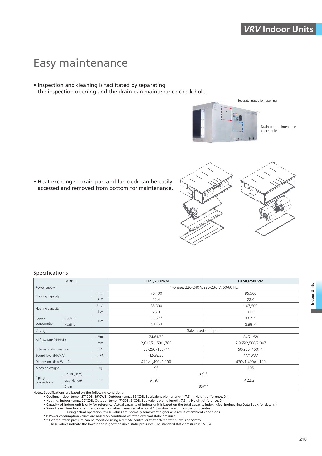
Easy maintenance
• Inspection and cleaning is facilitated by separating
the inspection opening and the drain pan maintenance check hole.
Separate inspection opening
Drain pan maintenance
check hole
• Heat exchanger, drain pan and fan deck can be easily
accessed and removed from bottom for maintenance.
Specifications
MODEL FXMQ200PVM FXMQ250PVM
Power supply 1-phase, 220-240 V/220-230 V, 50/60 Hz
Btu/h 76,400 95,500 Cooling capacity
kW 22.4 28.0
Btu/h 85,300 107,500
Heating capacity
kW 25.0 31.5
Power Cooling 0.55 *1 0.67 *1
kW
consumption Heating 0.54 *1 0.65 *1
Casing Galvanised steel plate
m3/min 74/61/50 84/71/58
Airflow rate (HH/H/L)
cfm 2,612/2,153/1,765 2,965/2,506/2,047
External static pressure Pa 50-250 (150) *2 50-250 (150) *2
Sound level (HH/H/L) dB(A) 42/38/35 44/40/37
Dimensions (H × W × D) mm 470×1,490×1,100 470×1,490×1,100
Machine weight kg 95 105
Liquid (Flare) 9.5
Piping
Gas (Flange) mm 19.1 22.2
connections
Drain BSP1”
Notes: Specifications are based on the following conditions;
• Cooling: Indoor temp.: 27°CDB, 19°CWB, Outdoor temp.: 35°CDB, Equivalent piping length: 7.5 m, Height difference: 0 m.
• Heating: Indoor temp.: 20°CDB, Outdoor temp.: 7°CDB, 6°CDB, Equivalent piping length: 7.5 m, Height difference: 0 m
• Capacity of indoor unit is only for reference. Actual capacity of indoor unit is based on the total capacity index. (See Engineering Data Book for details.)
• Sound level: Anechoic chamber conversion value, measured at a point 1.5 m downward from the unit centre.
During actual operation, these values are normally somewhat higher as a result of ambient conditions.
*1: Power consumption values are based on conditions of rated external static pressure.
*2: External static pressure can be modified using a remote controller that offers fifteen levels of control.
These values indicate the lowest and highest possible static pressures. The standard static pressure is 150 Pa.
210
stinU
roodnI
FACING PAGE — PDF page 210
High Static Pressure Duct Type
FXMQ-P
High static pressure allows for flexible duct design.
Design flexibility
Adjustable external static pressure
• Using a DC fan motor, the external static pressure can be
controlled within a range of 50 Pa to 250 Pa.
Adjustable external static pressure
50Pa 250Pa
Easy installation
“Airflow rate auto adjustment function” at field setting
(local setting by remote controller)
Rated airflow
Built-in pre-filter slot
• To cater for easy installation of filter at site,
a filter rail is available at the return flange.
209
)PSE(
erusserp
citats
lanretxE
Duct resistance at
designing system
rpm 1
*This function can only be set via wired remote controller. Actual duct
resistance
rpm 2
Field setting Various adjustments are required
without “airflow rate (Due to excess or deficiency of
Design Installation airflow) e.g. Duct re-construction,
auto adjustment function”
Motor replacement, Damper
replacement, etc.
rpm 7 System
operation
Field setting Innovating
rpm 8
with “airflow rate Function!
Design Installation
auto adjustment function”
by remote controller
Airflow
<Mechanism>
1. During field setting, power input of DC fan is detected.
Notes: ”Airflow rate auto adjustment function” can be adjusted within ±10% of rated
2. External static pressure is estimated from power input of DC fan because PCB
airflow. (Refer to Engineering Data Book for details)
of FXMQ-P has table of external static pressure vs. power input of DC fan.
”Airflow rate auto adjustment function” should be used at field setting only.
3. Actual duct resistance is calculated according to 1 and 2.
4. Fan speed is automatically adjusted to produce rated airflow.
Catalogue article on VRV.vn ↗ · Original English PDF on VRV.vn ↗
SAME SERIES · FXMQ-P